Kawasaki Versys Forum banner

Stator Output/ Stator Testing/ Device load Ratings 2015

19K views 88 replies 12 participants last post by  onewizard  
#2 · (Edited)
Use Post 14 and video post 16 for testing, and post 34 in reference to China Stator RM Stator


At some point I will extract all the testing and place it in an appropriate thread. For now, this is going to do it for me.
More of a simple, very quick and extremely accurate test, to prove if any stator damage has occurred.

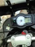
Basically, use your idle adjustment screw and get the RPM around 2000 RPM, this is warmed up RPM, do not try holding the throttle and measuring this.

So depending how fast you are, you may need to hook up your battery tender.

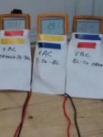
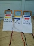
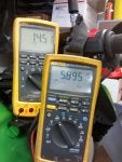
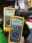
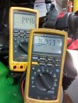
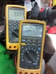
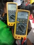
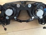
So what you need is some fine jewelers screwdrivers, straight pins or something that can be inserted in your socket of the stator plug, also a meter that reads volts AC, preferably with alligator clips on the probes . This is the 3 wires coming from the stator, to a plug close to your throttle position sensor. This connector has a latch locking it together, to release you need to squeeze down on the latch and wiggle / pull at the same time. When apart you are measuring the output from the stator under no load conditions, for your purpose, make a drawing and identify the 3 female crimps as #1,#2,#3, as long as you know what you are calling when referencing your measurements. So at 2000 RPM measure 1 to 2; 2 to 3; 3 to 1******that is your 3 readings, they should be around 24 to 28 VAC at 2000 RPM, the readings should be 0.5 VAC within each other, that is 1==28.0; 2==27.5; 3 ==28.3----

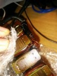
-if any readings are like the following ****1==24; 2==16; 3==22, you have shorted turns.

There is a third test that can also be done, measure 1,2,3 to ground, record these three readings, should be around 17 volts AC


Note:
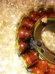
One thing I have never mentioned, between my test and Kawasaki. Kawasaki requests 4000 or 5000 RPM, at that speed the rotor is producing maximum flux density, at 2000 RPM it is about 35% of maximum.


Note Added This in February 2017 To Test for Phase Loss on a Series regulator under Actual Load Conditions


Added additional info March 2019


in reference to testing Polaris regulator 4012941 and Polaris 4016868 , both have the same pin configuration except the 4016868 has less losses and a lower forward voltage drop / loss .

For those trying to test to see if the Polaris regulator is OK, a initial crude test would be to use a ohmeter on the 3 phase input, A-B,B-C,C-A all should be in excess of 1 million ohms. You can then hook up the 3 phase input to your stator and follow the 2000 RPM test, only difference is do not connect the battery to the Polaris output. With the bike running you should get no output, also if your battery is at or below 8 VDC I recommend charging the battery first as the Polaris has reverse polarity and low voltage protection built in.

It will not output any VDC no matter even if you are 48 VAC input and 4000 RPM, without having the correct VDC polarity at 8 VDC or greater connected to the output ( this is used to fire the SCR gate pulses) . Lastly connect the proper polarity with a semi or fully charged battery, at 2000 RPM you should get 14.2 VDC with the bike running and base load ( including low beam headlight). At this time you can follow my 3 phase input testing below, be aware not all meters can recognize the 3 phase as it is being rapidly switched, if your VAC readings are within a volt on all 3 phases and you are getting 14.2 VDC out, all is good!!

Original before March 2019;
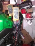
A better way would be using a small AC clamp on current probe rated for 400 HZ @ 25 Amp AC, pretty sure no one on this forum has one.So I came up with this:
This test is to prove all 3 phases of a Series regulator are functioning, such as Polaris or Compu Fire. What you will need is some straight pins, needles or jewelers screwdrivers, to insert from the stator wire side of the connector. You are measuring VAC, you need to set idle around 1800 to 2000 RPM, have the headlight on, measure A to B, B to C, C to A , record the readings, they should all be around 16 to 18 Volts AC , battery voltage should be 14.2 VDC. If you get one of the phases reading 22 to 24 VAC or more, that phase isn't conducting/ being fired, which means you have a single phase condition on the stator. The stator is rated at something like 24 amp output, phase current is rated at 14 amp maximum, if you have a phase loss, you will get a single phase condition, with a maximum 24 amp available, hence the burnt stator.

If you have any questions ask me. Very little about induction I don't know, that has been my specialty for over 40 years.
The difference is that, at 25% flux density, a small turn to turn short or turn to line short will have a large impact on the AC output. At 100% output, the imbalance between phases will be less noticeable.
 

Attachments

  • Like
Reactions: mikesundrop
#3 ·
Regulator / Shunt verses Series

I got a couple questionable looks today when I mentioned I am replacing my brand new 2015 regulator. I like where they mounted it, however one consideration I would suggest is to extract the pins from the OEM socket, cut the wire at the crimp, all wiring is way too short. You could order the socket kit from the post above if you wanted to restore to original, word of caution, that style of crimp requires a special crimper. I will post pictures of how I did my compufire and you could do the same for Polaris.

So, the main event:
Most equipment whether a electric motor or what is referred to as switch gear, or outlets in your home have a rating. Your duplex outlet is on a 15 amp breaker, the wire is rated to carry 15 amp, 15 X 120 = 1800 watts, however most equipment on that 15 amp circuit has a rating of 1500 watts or less.
Your wiring and breaker etc has a 80% rating, that is it isn't rated to carry 1800 watts continuously, which is 100% rated . Most equipment is rated the same way, throw in a higher ambient temperature and you need to de-rate your equipment even more--so that 80% rating becomes 70% or 60%.I hope this makes sense.
Much like a human being, hot weather and exposure to the sun , heat stroke is possible and precautions need to be taken, this applies to everything electric, heat is number one killer--you've heard "the magic smoke escaped", so having a crude electrical regulator in 2016 where it forces the stator to run 100% whenever possible makes no sense, especially since technology has been around and produced for over 10 years ie. Compu-Fire for one.

So this is where it makes no sense installing a shunt regulator and rumors have it that the 2015 has more power--we'll see.
A shunt regulator makes the stater run at 100% all the time it is above 3000 RPM, and run at maximum available output below 3000 RPM

The series regulator , say your total load is 10 amp DC ( 40% load), injectors, fuel pump and headlight , city lights and tail light, ignition, and your cell phone.I picked 25 amp rather than 23 amp for calculation purposes --and don't know the rating of the 2015, ( 10 amp / 25 amp= 40%).

With the series regulator ,stater is running at 40% load all the time, no matter what the RPM, So which stater do you think will fail first the 40% loaded one or the 100% loaded one? Plus it isn't magic, conversion from HP to electricity is at best 50% efficient , so you are burning fuel to heat up the environment, wasting 60% of the electricity produced.

Still not convinced, at idle the shunt and series regulators are equal, generally the loads of the Versys are equal to or slightly less than stater output, when we go above idle, the shunt regulator shorts out the excess above 14.2 VDC. The series works in reverse, it is full on at idle giving what is needed to maintain 14.2 VDC , once we go above idle and attempt to exceed 14.2 VDC the series regulator starts to switch off, the higher we go in RPMs the faster it switches off, so the stator only sees the load demanded using the Series Regulator.

So the shunt regulator and stater are always going through a heat cool cycle as you go from idle to 5000 6000 RPM, so this eventually causes the magnet wire coating to fail --hence Burnt stator
 
#4 ·
Permanent magnet VS Car Alternator

Short story, using a series regulator on a permanent magnet stater is identical in load characteristics and function to a car alternator. Both keep up to the load demand . The difference is a car alternator controls the strength of the magnetic field so it is equal to the output required. If your car had a permanent magnet stater, and shunt regulator, you would hear the alternator whining all the time, just like when you had to boost the car because of a dead battery, except it would be whining because of outdated technology, and yes, you would experience alternator failure in cars on a much more frequent basis .
 
#5 · (Edited)
Stator Output 24 amp @ 14 VDC = 336 Watts


Note: December 2016**changed the values of VDC from 14.5 to 14.2 VDC This will cause the calculations done previously to be off, from what is posted***Typical shunt regulator puts out 14.5 to 15 VDC ( malfunctioning shunt regulators have caused ECU failure in the past, due to the fact they only start working / shunting @ or above 14.5 VDC, Series regulator is solid @ 14.2 VDC )


I am going to start by saying, I found some startling news as to the Osram 65 Watt bulb I am using, and may be going back to OEM for low beam.

To simplify and reduce text :
Base load=ignition;fuel pump; tail and license plate bulbs; (city lights are LED)= 5.89 ADC @ 14.2 VDC

Headlight = Osram super bright PX26D #64217 rated 65 Watt @ 12VDC, actual wattage @ 14.2 VDC=80 Watts BTW they are now obsolete 5.3 ADC @ 14.2 VDC

Base Load Total including headlight = 162 watts on my 2015


Add approximately 10 Watts if using incandescent city lights


***Approximate Watts Available above Base Load=174 Watts***


****Note , Subtract 10 Watts if you have OEM city incandescent bulbs instead of LED from Available Watts

All loads below are in addition to Base Load


High Beam Light is between 70 Watts for OEM and 80 Watts for Osram

Fan = 4.81 amp @ 14.2 VDC=70 watts

Heated Oxford Grips on Max=3.6 amp to 4 ADC ( each grip 28-30 watts maximum) @ 14.2 VDC = 56.8 Watts Maximum

Gerbing heated Jacket @ 77 Watts = 5.42 amp @14.2 VDC

Fluke meter displaying mVDC is being driven by a hall effect
clamp on amp probe that outputs 1 mV per amp DC, measured at the Compu-Fire regulator positive output wire.

Fluke meter showing VDC is connected to the battery terminals
Testing was done at 1500 RPM with base load and fan

Testing was done again @ 3000 RPM, with base loads and all other loads as described.


:nerd:

Note:
Since this bike has 6 KM on it, is strapped down on my lift and has no other cooling, beyond the rad fan, I felt it prudent to limit how fast and how long I ran this motor , picture #562 is what I would say is maximum output, you may gain 1 volt at 6000 RPM which would be 24 watts. My feeling is we are at saturation with the magnetic field at 3000 RPM. So what I will say is this stater has a maximum output of 348 Watts. Always keep in mind that your battery if less than 12.4 VDC becomes a continuous load. Something I will try and show once the stater is changed out on Smiley's bike.

:frown2:

#565 fan and base electrics
#549 showing regulator and amp clamp
#550 base electrics
#551 base electrics & Fan
#552 base electrics & Fan & low beam
# 553 base electrics, low & high beam
#554 base electrics, low & high beam & heated grips
#562 base electrics, low & high beam & heated grips & fan @ 3000 RPM

Below note updated 2018
Note; when viewing meters, pay attention to the one showing DC mv,the hall effect clamp on amp probe is 1 milli volt per amp,so in photo #554 it is 20.9 amps DC and #563 23.86 amp @ 13.46 VDC at 3000 RPM , increasing to 4000 RPM would bring the voltage up to 14.2 VDC, but we're nearing the output maximum of the stator.

Also in reference to incandescent verses LED, incandescent bulbs have a wattage rating at 12 VDC, a increase to 14.2 VDC will cause a increase in wattage , however the increase in wattage is not directly proportional to the voltage increase. LED bulbs are either fixed current or in the case of headlight bulbs have a driver and a rating of 9 to 32 VDC, the wattage will remain the same no matter what the voltage, however a increase in voltage is inversely proportional to the decrease in current.
 

Attachments

#6 ·
I am going to start by saying, I found some startling news as to the Osram 65 Watt bulb I am using, and may be going back to OEM for low beam.

To simplify and reduce text :
Base load=ignition;fuel pump; tail and license plate bulbs; city lights are LED 5.89 ADC @ 14.5 VDC

Headlight = Osram super bright PX26D #64217 rated 65 Watt @ 12VDC, actual wattage @ 14.5 VDC=80 Watts BTW they are now obsolete 5.3 ADC @ 14.5 VDC

Fan = 4.81 amp @ 14.5 VDC=70 watts

Heated Oxford Grips on Max=3 amp @ 14.5 VDC


Fluke meter displaying MvDC is being driven by a hall effect
clamp on amp probe that outputs 1 Mv per amp DC, measured at the Compu-Fire regulator positive output wire.

Fluke meter showing VDC is connected to the battery terminals
Testing was done at 1500 RPM with base load and fan

Testing was done again @ 3000 RPM, with base loads and all other loads as described.


:nerd:

Note:
Since this bike has 6 KM on it, is strapped down on my lift and has no other cooling, beyond the rad fan, I felt it prudent to limit how fast and how long I ran this motor , picture #562 is what I would say is maximum output, you may gain 1 volt at 6000 RPM which would be 24 watts. My feeling is we are at saturation with the magnetic field at 3000 RPM. So what I will say is this stater has a maximum output of 348 Watts. Always keep in mind that your battery if less than 12.4 VDC becomes a continuous load. Something I will try and show once the stater is changed out on Smiley's bike.

:frown2:

#565 fan and base electrics
#549 showing regulator and amp clamp
#550 base electrics
#551 base electrics & Fan
#552 base electrics & Fan & low beam
# 553 base electrics, low & high beam
#554 base electrics, low & high beam & heated grips
#562 base electrics, low & high beam & heated grips & fan @ 3000 RPM

The Kawasaki spec is: 14 V – 24 A @5 000 r/min (rpm)

That is 336W. The Kawasaki spec is probably pretty conservative, so it matches up well with your numbers.
 
#7 · (Edited)
Osram 65 watt obsolete actual is 80 watt / Energy 101

FYI for any following this thread, I changed my low beam back to stock on the 2015, for two reasons, the 65 watt are no longer made and have been replaced with 80 watt, plus the actual wattage when stater is under normal output @14.5 VDC , the wattage is 80 watt, all bulbs have a 12 VDC rating, the wattage displayed is what you will draw at 12 VDC .

Due to the fact it is a tungsten filament it is not the same as calculating the load of a fixed resistor.A 1.2 ohm resistor at 12 VDC / 1.2 ohm = 10 amp

10 amp X 12 VDC = 120 watts

If the resistor was 2.4 ohms = 5 amp or 60 watt.

Tungsten filament is an non linear load, that is if you measured a 100 watt light bulb resistance would be about 12 ohms

120 VAC / 12 ohms = 10 amp ***10 amp X 120 VAC = 1200 watts, yes 1/10 th the resistance cold, that is why you see lights blink when turning on a light fed from the same circuit that already has a light on, called inrush current.
Here we go:rolleyes:

Old soon to be obsolete technology:

For those that have what is referred to as toggle dimmers or slide dimmers used on incandescent lights, you will notice the bulbs last 3 times longer. The reason is, all these style of dimmers start at near zero volts and raise to maximum or your light level required and heat the filament up under lower voltages / lower currents, 15 to 30 micro seconds , so the filament doesn't have as high a inrush current == longer life:nerd: soon to be replaced by LED technology.
 
#10 ·
Couple Forum user tried this


There were several postings of some members working with these people , the thread died and it all vanished .

Some of the problems and solutions; when it fails and you are in the dark, you can;

#1 you can use high beam
#2 try and move high beam into low beam socket, good luck with that on any version with the size of that

#3 wait until the sun comes up
#4 claim under warranty--yes you can prove you followed instructions--again good luck
#5 keep a stock of them on the bike, they are really cheap--
#6 just leave the inefficient tungsten lamp in until they come out with a super conductor for the led

#7 wait for Kawasaki to incorporate a heat sink in the reflector to allow a standard Cree LED-- yes that is going to happen just like the new 2015 650 ABS Series regulator not really

Just like the hid lamps I am all for led technology, more lumens , =less wattage=more power for other things. HID same thing, all made in China, numerous failures and not reliable, plus the reflector was never designed to handle HID.

Many LED manufacturer's give wattage rating but no lumens or lumen rating and no wattage, one without the other is meaningless.
 
#9 ·
LED Technology / HEAT

LED been around over 26 years, high output led Cree been around 3 years roughly, you can correct me, my point, until reliability and losses in the form of heat, the only reliable method for 2200 lumen output or higher is with fan cooling.
The motorcycle is different from a car in that much less room and very little allowance for increased real-estate to allow for cooling.
The 2015 doesn't have the H7 adapter, and there is very little room behind the existing bulb, last thing there is a lumen output rating but I didn't see a wattage rating at a specified voltage.
 
#11 · (Edited)
I agree that 98% of the LEDs are unreliable crap, and one needs to be diligent to find the 2%.
So how about a duel, Mr. onewizard.
I am going to upgrade to their 3200 lumen to use as low beam, and I will send you my 2200 lumen with proper connectors.
The challenge is this: If either of us blows an LED, you win; if the LEDs outlast the bikes, I win.
So, what do you say? If it magically appears on your door step, will you give it a try? Your stator will thank you.

Edit: I think I remember reading somewhere that each emitter on the 2200 lumen is 10 watts, for a total of 20. The 3200 lumen has two 15 watt emitters.
http://www.cyclopsadventuresports.com/H7-3200-lumen-LED-Headlight-bulb_p_86.html
There is a fun video at bottom showing these being submerged in a glass of water.
 
#12 ·
Doing the math Watts / Lumens

I agree that 98% of the LEDs are unreliable crap, and one needs to be diligent to find the 2%.
So how about a duel, Mr. onewizard.
I am going to upgrade to their 3200 lumen to use as low beam, and I will send you my 2200 lumen with proper connectors.
The challenge is this: If either of us blows an LED, you win; if the LEDs outlast the bikes, I win.
So, what do you say? If it magically appears on your door step, will you give it a try? Your stator will thank you.

Edit: I think I remember reading somewhere that each emitter on the 2200 lumen is 10 watts, for a total of 20. The 3200 lumen has two 15 watt emitters.
H7 3200 lumen LED Headlight bulb
There is a fun video at bottom showing these being submerged in a glass of water.
I always question the ratings, similar to when IEC starters came out, 50 HP NEMA and 50HP IEC, not the same thing, it became apparent that increased protection had to be added for IEC, 20 years later NEMA has reduced contact size and the amount of copper metal in these starters, and IEC has decreased the HP rating to meet UL CSA standards.

So LED is roughly 1/5 the energy of a incandescent bulb or, 10X5 = 50 watt. I would think the light output is closer to 1500 lumens .

So two things, first I would be aiming at 2000 lumens minimum , second, from my pictures, there is a part of the frame support going almost directly behind the light, so I would think the whole front light assembly needs to be removed to install this. Second, the rubber boot also looks like it won't fit without modification, so restoring to original may not be a easy option.

Look for a PM
 
#13 · (Edited)
Current Rating / Wire gauge / Fuse Size/ Electrical 101

I thought I would do a little blurb for those interested and keep it in a thread that seems appropriate.

First under stand the relation between wire gauge, branch circuit wiring and device loading.
I will use a typical house with breakers or fuses the principle is the same.

The Main Breaker / Main Fuse is to protect the panel connections and the wire feeding the main. Say your service is 125 amp, if it was installed and approved for 100% loading, that would mean you can draw 125 amp, if it wasn't approved for 100% , it is then rated @ 80% = 100 amp continuous.

Take the number of breakers, say they all happened to be two pole and they were all 15 amp, say you had 20 breakers @ 15 amp = 300 Amp

What the breaker is designed to do is protect the wiring, again the 80% rule applies, hence the change to T slot receptacles and 12 gauge wire, 12 is rated at 20 amp X 80% = 16 amp @ 120 VAC = 1920 watts, many hair dryers, toasters, etc are 1800 watts.

Devices like a fridge, furnace, washing machine need a circuit of their own as they are motor loads and have large inrush currents. Between branch circuit protection and load specific protection more or less applies to motorcycles and fusing.

I have included a wire chart that very simply proves that two 18 gauge wires minus 3 is = to one 15 gauge.

So how I would like to explain it is if the wiring you are adding is going to be a distribution similar to your main breaker,

From your distribution point, say you ran 14 gauge = 15 amp

#1 using a 18 gauge = 5 amp
#2 using a 16 gauge = 10 amp
#3 using a 14 gauge = 15 amp
#4 using a 12 gauge = 20 amp
#5 using a 10 gauge = 30 amp

Your branch circuits from that point are load specific, for example heated grips load of 3 amp = 5 amp fuse
same distribution a heated vest of 6.8 amp = 10 amp fuse
" " a USB charger @ 1 amp = 3 amp fuse
so how you calculate how much you can add to your distribution point is take our example of 15 amp 80% loading = 11 amp***your total actual loads can sum up to 11 amp , so the above example would work fine and all the branch circuits would be protected

As well the wire gauge of the branch circuits would be reduced to for example the heated grips a 18 gauge wire.

I have included a wire gauge table that shows circular mills which is used to calculate circular mills per ampere .
AWG Wire Chart, Aught, MCM kcmil, US Inch, and Metric Wire Sizes


I also included a old thread , go to page 2 for my post there
http://www.kawasakiversys.com/forum...technical-discussion/893-you-electrical-folks.html?highlight=emergency+lighting

You will find calculations for emergency lighting, this will come as a surprise to most since the smallest wire gauge is #12, many do not realize the losses in energy that goes into the wiring instead of the light or heated grips because the wire gauge is insufficient . The second chart by Twowheel is also valid and applies more so to motorcycles, as many wires are 2 feet or less on a bike, one word of caution, using a larger gauge when the table says 16 or 14 for the same length, if the device can accept 14 gauge, that is the way to go, if you can only get 16 gauge pins, then this is also acceptable.

http://www.astralitelighting.com/PDF/WireSelectionChart.pdf
 
#14 · (Edited)
#15 · (Edited)
Stator Testing '/ Permanent Magnet Induction Testing 101

Every once in a while it becomes obvious I haven't done a good enough job explaining myself, I will say I am a induction specialist ( closest thing I know of to a expert).

So the only accurate way to test a stater in place using permanent magnets is using a rotating magnetic field at a fixed RPM and measuring open circuit voltage phase to phase. FYI OEM is Delta connected, ungrounded, after market is generally Y connected ungrounded.The reason why you can't accurately measure or test is, the magnetic full field is present even at rest / standstill.

Only accurate way to test a stater on the bench is using a LCR meter, not a ohmmeter.

So why a LCR meter, take the number of turns per pole 44 times 6 = 264 turns,Stator Rewinding

divide that into the manual spec resistance of 0.18-0.27 ohms which = .000681 to .0010 ohms per turn, lets go out on a limb and say one pole is completely shorted 0.27 divided by 6=0.045 ohms, let me tell you your leads average 0.25 to 0.50 ohms, so even if you know how to zero your leads, we are talking 0.027 minus 0.045 =0.22 ohms .

Using my method at a fixed RPM will detect even 1 shorted turn, or 1/264 of the effective impedance of the winding, your choice , follow the manual or follow my test method.BTW I don't own anything that will measure 0.045 ohms in place on a inductive load.
Simple explanation : using the open circuit 2000 RPM test--all readings should be within 0.5 volts AC and within 22 to 30 VAC, other-words, you measured A-B =22VAC, B-C =22.5 VAC and C-A =21.5 VAC would indicate stater is good


Simple explanation : using the open circuit 2000 RPM test--all readings should be within 0.5 volts AC and within 22 to 30 VAC, other-words, you measured A-B =22VAC, B-C =22.5 VAC and C-A =21.5 VAC would indicate stater is good

Same test method---A-B = 16 VAC , B-C = 4 VAC, C-A = 2 VAC == Your stater is toast

Same test method --A-B==26 VAC, B-C = 16 VAC , C-A = 19 VAC ==Your stater is toast


BTW reference previously about a grounded stator, except for measuring VAC while running, any pole to ground will measure to ground on all three phases. A little trivia, the Versys stater has 3 phase delta wound, each phase has six poles= a total of 18 poles with 44 turns of 18 gauge magnet wire, for pictures click on stator rewinding and see Fuse_x detailed post c/w pictures.


Note:
I have added a few more tests discussed in this thread, due to the fact the OP couldn't post in technical forum
:https://www.kawasakiversys.com/foru.../5-member-introductions/114761-lurking-awhile-finally-posting-looking-help.html


And another thread started where rather than read, just post another thread, posted in Burnt Stator and here:
https://www.kawasakiversys.com/forums/9-technical-discussion/115977-stator|r-r|battery-trouble-shooting.html
On the up side, some good info from Google, however somewhat complicated and not 100% correct instating the regulator is at fault for failure, it should read the shunt design is at fault
 
#16 ·
Meter Testing 101

Generally when using a meter, two settings are generally used for static testing, ohms in the range the manual of the versys states, if you have a good or more sophisticated meter, in ohms, short out your leads and hit REL which stands for relative, this will zero out the resistance of your leads, so the reading you take will be the actual reading.

For those without this feature, figure 0.50 to 0.75 of a ohm for leads.Second thing is diode test, used for checking diodes, a diode is typically 0.50 to o.80 of a ohm, using ohms will not give a accurate reading, however if that is all you have then if you were testing the regulator, one direction would be infinity ( reverse ) and the other would read possibly 3 to 5 ohms ( forward conduction), all tests are close to the same then all is good.

Last testing would involve measuring VAC or VDC.

So unless you were applying a outside power source like jumping your battery or you had a very old analogue meter, chances of doing damage by using a digital meter connected to the wrong thing with the wrong polarity, doing damage is virtually impossible! What you should gain from this is that odd readings usually mean either damage or you may have;the wrong colour code of wires and wrong shape of plugs, not traced the wire to the right area, or didn't follow direction.:surprise:
 
#18 ·
As to the video Skypilot 69, excellent, I would change only one thing, and that is the VAC testing of the 3 phase should be done using the idle adjustment screw, setting at a fixed approximately 2000 RPM. I have stated in other posts why I picked this RPM, and not the RPM called for in the manual. Short answer is shorted turns will show up at lower RPM because the stator is just beginning to produce approximately the same maximum voltage that it would under load. 2000 RPM should output 24 to 28 VAC and all readings should be within 0.5 VDC of each other.
 
#19 ·
More Stator Testing Info

So I have added a extremely well done video compliments of Skypilot 69, I have added comments of my own referring to using 2000 RPM using the idle screw.

http://www.kawasakiversys.com/forum...m/forums/9-technical-discussion/115977-stator|r-r|battery-trouble-shooting.html
SEE Post # 7 for the video


And a few pictures of a voltage monitor I now use on my 2015 ;
http://www.kawasakiversys.com/forum...chnical-discussion/116313-how-long-far-can-you-ride-battery-without-stator.html
 
#20 ·
Talking Stator Mounting or Lead clamp?

http://i198.photobucket.com/albums/aa4/jeandr_photo/IMG_3352_DxO_zps0pf0yrrq.jpg
Have a look at the above picture, I think you are referring to the below picture, which has a locating pin in the bottom.
http://www.kawasakiversys.com/forums/attachment.php?attachmentid=10345&stc=1&d=1300053225

If it is the second picture:
Well I did more research and realized my original suggestion may not work, because the tap drill for M6 is larger than#7.Rather than delete I thought I would leave it contained in {}. So the best option is to get a 7mm X 8mm hex bolt ( readily available size is M 7X8mm), get the taps as suggested below but M7. I have included a tap drill chart, in reality, very little force is required as this plate is to hold the wires toward the housing, this bolt is at right angles to the force applied, as is the pin in the bottom, manual says not to apply a locking agent such as loctite, JB weld might have worked, although I would take a chance, not because of the wire, more so the bolt coming out and getting in the gear box CRUNCH
http://www.lincolnmachine.com/tap_drill_chart.html >:):rolleyes::goodluck:

Note My suggestion is to go with a M7 taper and bottoming tap, However
the outside diameter of a M6 bolt is .233 inches, a 1/4 bolt is .250, however it likely will be .245 , so you would have a gain of about .006 per side of thread---not nearly enough. One other thing, measure the depth of the hole to the top and compare it to the bolt length, it might be deeper than the bolt length of the M6 X 16 mm . You could then get a longer M6 and cut the bolt shorter to match the depth.


{the bolt is a M6X8mm, I am going to suggest if you are really careful, you could buy a 1/4 by 5/8 hex bolt, or a 1/4 by 3/4 hex bolt and washer it down to 5/8. You need a 1/4 NC taper tap and a 1/4 NC bottoming tap. This is a blind hole, 1/4 turn past bottom and you strip the threads. There is another thing you could try, and that is a 1/4 self tapping hex bolt X 5/8, be aware that this is hardened, it is not meant to give a full depth thread, and any taping into aluminum requires lube and patience, plus it doesn't cut a thread very well and could cause the aluminum to crack from outward pressure.
My first choice would be the taps, the taper is strictly to get a few threads started, continue until you reach bottom, best to put a ring of tape around the tap, equal to the total drilled depth, if you have a mini grinder, you can grind the end of the taper tap , to the start of the first full thread, once you have started, not the same as a bottoming tap but close.

If it was somewhere else at a greater depth you could use a helicoil, trying that here would result in my third suggestion, that is you would likely bust through the housing if that happened I would suggest getting a longer M6 bolt, drill through the housing using a slightly undersized bit, tap it with a full thread. Insert the bolt and snug it by hand, take a file or hacksaw and mark the thread , remove and cut off to this length , file any burrs , if you have a nut, place it on the bolt before cutting, this way if there is a burr you will know by the fact the nut won't come off by hand, or if you are really brave zip cut it off while in place, not a good idea, as any burrs will possibly strip the thread on removal.Next step would be to attach the plate and apply either pro dope ( pipe sealant ) or some other thread sealant / gasket maker. Be aware with this sealant on the threads, tightening torque will be reduced, make it snug, once the pipe dope cures, it ain't moving.}
 
#21 ·
I'm opting for just buying a new stator cover, as the tools and pain the ass of trying to tap it and all that and make sure it works are about the same price as the new part, and sorta iffy. Got a new bolt too just to be sure.

This also frees me up to do whatever I need to this one to make it work and/or try fixing the part without worry about my transport being out of commission.

But the more pertinent question is - can I ride the bike this weekend to get to work...

I suppose it's difficult to gauge if the screw will come out or not, and it seems the risks are pretty high as there's a lot of fast moving parts in there... seems like just 2 of the gears in there run over 80 bucks each... *sigh*

If I put some jb weld all over the in the screw, think it'll stay? I have a new cover, bolt and even plate coming in the mail already... Could even jb weld the plate to the case... but I guess the even the jb weld could come off inside, eh?

It seems like the alternator lead wire bracket is pretty important to keep the stator wire from rubbing on the rotor, yeah?

I haven't even opened it back up (I just put everything back together since I don't actually have a garage to work in), to see about getting the bolt out.


Here's the old stator, which was indeed burnt:
Image

Image

Image

Image

Image

Dropbox link for full res: https://www.dropbox.com/sh/wr32bm1ekncebp8/AACdhnF7lLPuXUTJBWrQLC9ha?dl=0
 
#22 ·
onewizard - thanks again!
It is indeed the screw pictured in the bottom image.


What did you say about loctite? loctite is a 'non-permanent locking agent', yeah?

I'm not quite sure what you mean by this:


It sounds like you are suggesting starting with the taper tap and finishing with the bottoming tap. You said put a ring of "tap" around the tap, but now I'm figuring it out you mean tape so I can tell when it's in there so I don't bottom it out and keep turning (now I know a blind hole is one with a bottom).

*sigh* :p

Also, how do you suggest I actually get the screw out? Do you think it will come out easily, or just with some pliers, turning it and pulling?
Here is a suggestion, if you have a machine shop nearby, take it there, they may be able to help you. I just verified the length as you stated of 8 mm, that would be a bottoming tap only!

One last suggestion, if you have a drill and a 1/4 taper tap, a 6mm tap would work but finding metric fasteners may be difficult. So what I am going to suggest is buying a set screw that is equal to the distance from the outside cover to the inside edge, plus the thickness of a 1/4 nut. What you do is drill with a #7 drill bit or one size smaller and tap the hole to 1/4 inch NC ( 1/4 X 20 thread pitch or National Coarse ), insert the allen screw with plenty of permanent loctite placed on the last 4 threads as you screw it in from outside , you have now created a stud, the loctite acts as a sealant and prevents the stud from turning once cured


So about a hour later you can proceed with putting the nut on inside, using blue non permanent loctite, FYI when assembling any of this, use brake cleaner to remove any traces of oil or lube, otherwise it may not set properly.

FYI this is a 18/8 stainless set screw, I included a link so you understand and as a example, a 1/4 NC thread pitch 20 would be a number 7035 for 1 inch long,on the site
https://www.boltdepot.com/Set_screws_Allen_Cup_point_Stainless_steel_18-8_1_4-20.aspx?nv=l

:goodluck:
 
#23 ·
This seems like a good solution, no?
https://www.amazon.com/TIME-SERT-Me...2K/ref=sr_1_12?s=automotive&ie=UTF8&qid=1473261365&sr=1-12&keywords=helicoil+m6

And why not use a Helicoil?
https://www.amazon.com/Helicoil-554...Thread/dp/B0002KKPXK/ref=pd_sbs_263_1?ie=UTF8&psc=1&refRID=E3HYQTRQ48FA0W5THN2W

UPDATE:
Decided to get the Time-Sert kit, and fancy new drill from Amazon with overnight shipping and see how rearing goes, if I'm lucky I can get it repaired before the weekend and before the new stator cover arrives and just re-sell or see about returning the replacement parts. :)

onewizard, I'm a bit confused by your last suggestion, are you suggesting a set screw from the side? That's a neat one.

Ultimately, I'm just gonna leverage amazon's overnight shipping and I think the Time-Sert may be the best possible option next to replacement anyhow (though price wise, it's only marginally better than replacement).
 
#24 ·
http://i198.photobucket.com/albums/aa4/jeandr_photo/IMG_3352_DxO_zps0pf0yrrq.jpg
Have a look at the above picture, I think you are referring to the below picture, which has a locating pin in the bottom.
http://www.kawasakiversys.com/forums/attachment.php?attachmentid=10345&stc=1&d=1300053225

If it is the second picture:
Well I did more research and realized my original suggestion may not work, because the tap drill for M6 is larger than#7.Rather than delete I thought I would leave it contained in {}. So the best option is to get a 7mm X 8mm hex bolt ( readily available size is M 7X8mm), get the taps as suggested below but M7. I have included a tap drill chart, in reality, very little force is required as this plate is to hold the wires toward the housing, this bolt is at right angles to the force applied, as is the pin in the bottom, manual says not to apply a locking agent such as loctite, JB weld might have worked, although I would take a chance, not because of the wire, more so the bolt coming out and getting in the gear box CRUNCH
Tap Drill Chart >:):rolleyes::goodluck:

Note My suggestion is to go with a M7 taper and bottoming tap, However
the outside diameter of a M6 bolt is .233 inches, a 1/4 bolt is .250, however it likely will be .245 , so you would have a gain of about .006 per side of thread---not nearly enough. One other thing, measure the depth of the hole to the top and compare it to the bolt length, it might be deeper than the bolt length of the M6 X 16 mm . You could then get a longer M6 and cut the bolt shorter to match the depth.


{the bolt is a M6X8mm, I am going to suggest if you are really careful, you could buy a 1/4 by 5/8 hex bolt, or a 1/4 by 3/4 hex bolt and washer it down to 5/8. You need a 1/4 NC taper tap and a 1/4 NC bottoming tap. This is a blind hole, 1/4 turn past bottom and you strip the threads. There is another thing you could try, and that is a 1/4 self tapping hex bolt X 5/8, be aware that this is hardened, it is not meant to give a full depth thread, and any taping into aluminum requires lube and patience, plus it doesn't cut a thread very well and could cause the aluminum to crack from outward pressure.
My first choice would be the taps, the taper is strictly to get a few threads started, continue until you reach bottom, best to put a ring of tape around the tap, equal to the total drilled depth, if you have a mini grinder, you can grind the end of the taper tap , to the start of the first full thread, once you have started, not the same as a bottoming tap but close.

If it was somewhere else at a greater depth you could use a helicoil, trying that here would result in my third suggestion, that is you would likely bust through the housing if that happened I would suggest getting a longer M6 bolt, drill through the housing using a slightly undersized bit, tap it with a full thread. Insert the bolt and snug it by hand, take a file or hacksaw and mark the thread , remove and cut off to this length , file any burrs , if you have a nut, place it on the bolt before cutting, this way if there is a burr you will know by the fact the nut won't come off by hand, or if you are really brave zip cut it off while in place, not a good idea, as any burrs will possibly strip the thread on removal.Next step would be to attach the plate and apply either pro dope ( pipe sealant ) or some other thread sealant / gasket maker. Be aware with this sealant on the threads, tightening torque will be reduced, make it snug, once the pipe dope cures, it ain't moving.}
These are great suggestions. :thumb:
On old school Suzukis, for stripped 6mm cam cap bolts, 1/4-20 (self tap bolts) got many riders out of a bind and lasted forever. No drilling, no tapping... just carefully screw in the self tapping 1/4-20 bolt. :)
Note: Later on, if the head was off for whatever reason, it was time to tap, helicoil, etc.
 
#25 ·
Helicoil / Thread repair
https://www.amazon.com/TIME-SERT-Met...vert-amazon-20

Helicoil is a brand name that first invented a thread repair method.
Will not work because you don't have the depth or the outside diameter of material to work with.

My last suggestion of a stainless 18/8 set screw will definitely work provide you are careful not to over torque the nut when assembling. From the outside you will see a stainless set screw you never saw before, total cost would be less than $20, if you have the tap and drill bit less than $1 provided you have loctite.
 
#26 ·
Looked at Pictures /Close up of lead side would help

If possible get a close up of the lead side where the leads are connected, this is typical of stator failure, however this is the newer version stator with the cross connections on the rear. Same fault caused by expansion / contraction and heat load, all directly related to the shunt regulator POS.

By the way thanks for posting the pictures, I was beginning to think that someone joined the forum just to see if they could fool me into thinking all the above could possibly happen:eek:
So with the pictures that is proof enough you are really a Versys owner---every once in a while we all get a little :stickpoke: this helps to keep ones sanity when one can't ride due to the heat outside, today equal to 41'C with humid X

I hope all the suggestions help you out.
:yeahsmile:
 
#27 ·
Helicoil / Thread repair
https://www.amazon.com/TIME-SERT-Met...vert-amazon-20

Helicoil is a brand name that first invented a thread repair method.
Will not work because you don't have the depth or the outside diameter of material to work with.

My last suggestion of a stainless 18/8 set screw will definitely work provide you are careful not to over torque the nut when assembling. From the outside you will see a stainless set screw you never saw before, total cost would be less than $20, if you have the tap and drill bit less than $1 provided you have loctite.
No drill or tap (until the kit comes in the mail). Is it true that there's no space? I guess I'll find out soon.

I may try the 1/4-20 self tapping screw. onewizard suggested it might crack the aluminum, but I'm willing to risk that as I already have a replacement cover in the mail. Thanks for putting in another vote there, quexpress


So get this... when I went to torque the allen keys I realized my allen key socket was 3/8, but my torque wrench was 1/4in... ironically this was after just hand tightinging the bolts, which I'm sure would have been fine...
But I undid them and re-did them with this tool:
A 5mm hex key 1/4 socket, 1/4in to 1/2in socket adapter, 1/2 socket extension, 19mm open/box wrench, 6mm hex allen key, 6mm hex 3/8 socket, torque wrench.

Ironically, it's not that I had the wrong tool for the job, but just that in the hustle with dark looming, after getting the stator screws set, I forgot to re-adjust the torque for the lesser bolt, and the higher torque stripped it... I didn't even think that I'd be so likely to strip it, but then, I just wasn't thinking about it...

unfortunately... I didn't stop to take pictures :p
 
#28 ·
So if you lived near by I would have done the repair for free, you spend no more than $2 for the stainless set screw, in fact I would have helped install it, as the time I wasted far exceeds the effort involved in repairing this, I say wasted but not really, someone else may be able to use this info. What does bother me is the deleted post you made, which I automatically get in my email, even after it gets deleted:

supaiku said:
"I'm opting for just buying a new stator cover, as the tools and pain the ass of trying to tap it and all that and make sure it works are about the same price as the new part, and sorta iffy. Got a new bolt too just to be sure.

This also frees me up to do whatever I need to this one to make it work and/or try fixing the part without worry about my transport being out of commission.

But the more pertinent question is - can I ride the bike this weekend to get to work...

I suppose it's difficult to gauge if the screw will come out or not, and it seems the risks are pretty high as there's a lot of fast moving parts in there... seems like just 2 of the gears in there run over 80 bucks each... *sigh*"
Editing the post would have been the right thing to do, not deleting it, as all that responded have these posts in their email.I seriously doubt Kawasaki has this cover in stock, so expect 2 to three weeks ( 10 business days)
I here the frustration, for now your on your own. Enjoy your bike ,Wizard Over & Out
Indeed. It'd be great if I knew someone around here with this tools/skills.

It's difficult because apparently the hardware stores around here aren't very well stocked. I don't know any machine shops, though I suppose I could look into it. At this point time is getting limited.

FYI, the post wasn't deleted, it has the images on the previous page, I edited it. There's always email notification settings.
 

Attachments

#29 ·
Thanks for Posting& Updating Pictures

I would quote but since early July I get a busy script using FireFox, Chrome & Edge , so work around is quick replay then go advanced.PITA but Admin more or less says it ain't their problem.

OK :sorry:, so I edited my post, your quote shows the original which is fine, every once in a while I stick my foot in my mouth, all size 12, and I meant what I said about doing the work, I have enough 1/4 taps I could start a business, retired now so more free time.

So your photo with the cross over connections, it would appear it shorted out where the 3 phase lead connection is made, I have seen this on several stators, again the lead area is where the most heat is and has the least ability to cool due to the congestion, again I would say that if you had had a series regulator on your bike, chances of this happening would be 1 in 1000.JMHO

There has been some comment on other forums about oil level not being high enough, if you consider the leads connection is just slightly above center of the housing, this wouldn't apply here, and again the regulator is a contributing factor to this failure.
 
#30 ·
4012941 / Polaris / Not Mosfet

This has been covered before by me and many others, do a search and see if you find your regulator , search is either SH775 or 4012941, both numbers appear on the side of the regulator, this represents a series regulator, if you had gone back a page you would have seen it.
Your comment of working on the right side has been done but is totally unnecessary. The Polaris regulator you have is likely a shunt regulator, read post 32 of this thread, picture of the above numbers, anything else is shunt type unless you have a Compu-Fire . So I will provide a link on MosFet or Fet for short;

https://en.wikipedia.org/wiki/MOSFET

The difference between shunt and open also known a Series regulator please note this is technical, however the meaning of shunt refers to the bypassing or discharging of excess voltage / current., this is the manufacturer of the 4012941 Polaris regulator .
REG/RECT?Car Electronics Products?Product Information?SHINDENGEN ELECTRIC MFG.CO.,LT

I have also provided a link which again is technical, you will see the Fet Shunt and also below the Series also known as a SH775


ƒJƒ^ƒ�ƒO”Ì”„�b“d‘•�»•i�b�»•i�î•ñ�b�V“dŒ³�H‹ÆŠ”Ž®‰ïŽÐ

Last, since admin. thinks Sticky's are sufficient and Burnt Stators meets that demand, this thread was started by me to help others in the install of Series Regulators, more of a How To What would have been nice is to do your posting in Burnt Stators and edit this post with a link to that.