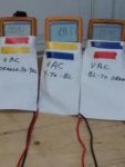
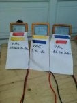
Use Post 14 and video post 16 for testing, and post 34 in reference to China Stator RM Stator
At some point I will extract all the testing and place it in an appropriate thread. For now, this is going to do it for me.
More of a simple, very quick and extremely accurate test, to prove if any stator damage has occurred.
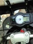
Basically, use your idle adjustment screw and get the RPM around 2000 RPM, this is warmed up RPM, do not try holding the throttle and measuring this.
So depending how fast you are, you may need to hook up your battery tender.
So what you need is some fine jewelers screwdrivers, straight pins or something that can be inserted in your socket of the stator plug, also a meter that reads volts AC, preferably with alligator clips on the probes . This is the 3 wires coming from the stator, to a plug close to your throttle position sensor. This connector has a latch locking it together, to release you need to squeeze down on the latch and wiggle / pull at the same time. When apart you are measuring the output from the stator under no load conditions, for your purpose, make a drawing and identify the 3 female crimps as #1,#2,#3, as long as you know what you are calling when referencing your measurements. So at 2000 RPM measure 1 to 2; 2 to 3; 3 to 1******that is your 3 readings, they should be around 24 to 28 VAC at 2000 RPM, the readings should be 0.5 VAC within each other, that is 1==28.0; 2==27.5; 3 ==28.3----
-if any readings are like the following ****1==24; 2==16; 3==22, you have shorted turns.
There is a third test that can also be done, measure 1,2,3 to ground, record these three readings, should be around 17 volts AC
Note:
One thing I have never mentioned, between my test and Kawasaki. Kawasaki requests 4000 or 5000 RPM, at that speed the rotor is producing maximum flux density, at 2000 RPM it is about 35% of maximum.
Note Added This in February 2017 To Test for Phase Loss on a Series regulator under Actual Load Conditions
Added additional info March 2019
in reference to testing Polaris regulator 4012941 and Polaris 4016868 , both have the same pin configuration except the 4016868 has less losses and a lower forward voltage drop / loss .
For those trying to test to see if the Polaris regulator is OK, a initial crude test would be to use a ohmeter on the 3 phase input, A-B,B-C,C-A all should be in excess of 1 million ohms. You can then hook up the 3 phase input to your stator and follow the 2000 RPM test, only difference is do not connect the battery to the Polaris output. With the bike running you should get no output, also if your battery is at or below 8 VDC I recommend charging the battery first as the Polaris has reverse polarity and low voltage protection built in.
It will not output any VDC no matter even if you are 48 VAC input and 4000 RPM, without having the correct VDC polarity at 8 VDC or greater connected to the output ( this is used to fire the SCR gate pulses) . Lastly connect the proper polarity with a semi or fully charged battery, at 2000 RPM you should get 14.2 VDC with the bike running and base load ( including low beam headlight). At this time you can follow my 3 phase input testing below, be aware not all meters can recognize the 3 phase as it is being rapidly switched, if your VAC readings are within a volt on all 3 phases and you are getting 14.2 VDC out, all is good!!
Original before March 2019;
A better way would be using a small AC clamp on current probe rated for 400 HZ @ 25 Amp AC, pretty sure no one on this forum has one.So I came up with this:
This test is to prove all 3 phases of a Series regulator are functioning, such as Polaris or Compu Fire. What you will need is some straight pins, needles or jewelers screwdrivers, to insert from the stator wire side of the connector. You are measuring VAC, you need to set idle around 1800 to 2000 RPM, have the headlight on, measure A to B, B to C, C to A , record the readings, they should all be around 16 to 18 Volts AC , battery voltage should be 14.2 VDC. If you get one of the phases reading 22 to 24 VAC or more, that phase isn't conducting/ being fired, which means you have a single phase condition on the stator. The stator is rated at something like 24 amp output, phase current is rated at 14 amp maximum, if you have a phase loss, you will get a single phase condition, with a maximum 24 amp available, hence the burnt stator.
If you have any questions ask me. Very little about induction I don't know, that has been my specialty for over 40 years.
The difference is that, at 25% flux density, a small turn to turn short or turn to line short will have a large impact on the AC output. At 100% output, the imbalance between phases will be less noticeable.


