Single Series resistor / Voltage Drop
I am pleased to announce that I was both right and wrong about the vehicle down sensor (VDS for short).
a) disconnecting the VDS is not a workaround. The checking time from the ecu is longer than 5 seconds. I suspect it is on some internal clock so it can be quick or slow. Feels more like 8 seconds.
b) the resistive hack WORKS! I rode 5 minutes. No issue, no odd lights. ECU completely fooled. And if I disconnect it wile running, bike turns off within the usual 8sec.
This is before putting duct tape to hold in place. Something more tightly fitting would be recommended, as it is rather unreliable like this, and not waterproof.
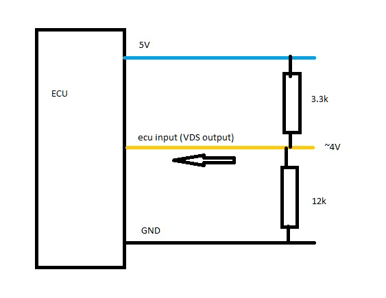
What I found is the ECU current from the output of the VDS is 36.45 micro amp as measured using a Fluke 189, on my 2015. Input voltage is 5.01 VDC as measured using a Fluke 189.
Voltage at the output of the VDS 3.98 to 3.99 VDC at idle running, with battery @ 14.2 to 14.3 VDC . I used a 32.6 K ohm resistor in series with the Blue and Yellow Green which gave a VDC 3.89 VDC ( voltage drop of 1.11 VDC) . I also used a 38.9 K ohm which produced a 3.73 VDC output ( voltage drop of 1.27 VDC). Both cases the bike ran for 5 minutes, when the wire fell out, it shut down around 7 seconds.
So both resistors are readily available. I have created a voltage drop equal to what the sensor input is,by measuring the current and by what I calculated ( original called for a 30,660 ohm resistor. The ones I used I had plenty in stock.
So if I would be a person heading out on a long trip with a MK-1 and you had similar trouble but it went away (
yes I would buy a new sensor however) as a backup you could first try either the 32.6K or the 38.3 K resistor, fold the ends over to double the thickness and insert between the Blue and Yellow
/ Green , measure VDC to ground from the yellow / green side of the resistor,if you are in the ball park of the values in the manual or those I displayed, pack a roll of electrical tape and I would suggest taping the resistor to the wiring harness of the VDS , give the tape a double rotation before ripping off, this is your start to remove the tape (the 2015 there is a frame ground less than 5 inches from the sensor)
36.55 micro amp DC Notice to the left of the 36.55 there is no triangle like the last photo, that is because one lead fell out and I keyed off, and noticed a error of 0.09 micro amps possibly induced, so the last photo I used REL to zero the display. ( ya I know, all gobbledygook :nerd: just remember, eventually some of this may sink in >
")
well if you read it enough) :huh:
Also note the photos from dddd are much clearer and easier to understand. And that is the difference between a Master Electrician with Electronics and a Engineer >
I am measuring between the left Blue 5.01 VDC supply in series with my Fluke meter on micro amps DC and the center input Yellow /Green
Using REL as there was a error of .09 micro amps with the leads disconnected, probably induced, but you will see a triangle to the left which indicates REL ( very similar to zeroing the resistance of the leads when measuring resistance)
Output of VDS @3.98 VDC
Using a single 32.6 K resistor between the Blue and Yellow 3.89 VDC
Using a 38.9 K resistor @ 3.72 VDC
Actual micro amps after using relative, really didn't need to but the meter read 0.09 micro amps high with open leads.