Kawasaki Versys Forum banner

Polaris Regulator / & Stator Testing/ Series/ 3 phase Rectifier & Video/ Series Legit or Fake?

11K views 7 replies 1 participant last post by  onewizard  
#1 ·
Stator Testing / Loading/ Polaris 4012941&4016868 Discussion Thread

Stator Output 24 amp @ 14 VDC = 336 Watts


Note: December 2016**changed the values of VDC from 14.5 to 14.2 VDC This will cause the calculations done previously to be off, from what is posted***Typical shunt regulator puts out 14.5 to 15 VDC ( malfunctioning shunt regulators have caused ECU failure in the past, due to the fact they only start working / shunting @ or above 14.5 VDC, Series regulator is solid @ 14.2 VDC )

Noted 2019 ;

Be aware if reducing loads by converting to LED, do this only if you have converted to a Series Regulator. The Versys has sufficient power to run heated grips and heated gear for a total of about 150 Watts. Expect to be discharging the battery when below 2500 RPM if running this gear.Reducing base loads on the shunt regulator, primarily converting to LED headlight and LED city lights , could cause shunt regulator failure


I am going to start by saying, I found some startling news as to the Osram 65 Watt bulb I am using, and may be going back to OEM for low beam.

To simplify and reduce text :
Base load=ignition;fuel pump; tail and license plate bulbs; (city lights are LED)= 5.89 ADC @ 14.2 VDC

Headlight = Osram super bright PX26D #64217 rated 65 Watt @ 12VDC, actual wattage @ 14.2 VDC=80 Watts BTW they are now obsolete 5.3 ADC @ 14.2 VDC

Base Load Total including headlight = 162 watts on my 2015


Add approximately 10 Watts if using incandescent city lights


***Approximate Watts Available above Base Load=174 Watts***


****Note , Subtract 10 Watts if you have OEM city incandescent bulbs instead of LED from Available Watts

All loads below are in addition to Base Load


High Beam Light is between 70 Watts for OEM and 80 Watts for Osram

Fan = 4.81 amp @ 14.2 VDC=70 watts

Heated Oxford Grips on Max=3.6 amp to 4 ADC ( each grip 28-30 watts maximum) @ 14.2 VDC = 56.8 Watts Maximum

Gerbing heated Jacket @ 77 Watts = 5.42 amp @14.2 VDC

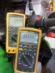
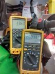
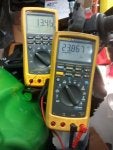
Fluke meter displaying mVDC is being driven by a hall effect
clamp on amp probe that outputs 1 mV per amp DC, measured at the Compu-Fire regulator positive output wire.

Fluke meter showing VDC is connected to the battery terminals
Testing was done at 1500 RPM with base load and fan

Testing was done again @ 3000 RPM, with base loads and all other loads as described.


:nerd:

Note:
Since this bike has 6 KM on it, is strapped down on my lift and has no other cooling, beyond the rad fan, I felt it prudent to limit how fast and how long I ran this motor , picture #562 is what I would say is maximum output, you may gain 1 volt at 6000 RPM which would be 24 watts. My feeling is we are at saturation with the magnetic field at 3000 RPM. So what I will say is this stater has a maximum output of 348 Watts. Always keep in mind that your battery if less than 12.4 VDC becomes a continuous load. Something I will try and show once the stater is changed out on Smiley's bike.

:frown2:

#565 fan and base electrics
#549 showing regulator and amp clamp
#550 base electrics
#551 base electrics & Fan
#552 base electrics & Fan & low beam
# 553 base electrics, low & high beam
#554 base electrics, low & high beam & heated grips
#562 base electrics, low & high beam & heated grips & fan @ 3000 RPM

Below note updated 2018
Note; when viewing meters, pay attention to the one showing DC mv,the hall effect clamp on amp probe is 1 milli volt per amp,so in photo #554 it is 20.9 amps DC and #563 23.86 amp @ 13.46 VDC at 3000 RPM , increasing to 4000 RPM would bring the voltage up to 14.2 VDC, but we're nearing the output maximum of the stator.

Also in reference to incandescent verses LED, incandescent bulbs have a wattage rating at 12 VDC, a increase to 14.2 VDC will cause a increase in wattage , however the increase in wattage is not directly proportional to the voltage increase. LED bulbs are either fixed current or in the case of headlight bulbs have a driver and a rating of 9 to 32 VDC, the wattage will remain the same no matter what the voltage, however a increase in voltage is inversely proportional to the decrease in current.
 

Attachments

#2 ·
Stator Testing '/ Permanent Magnet Induction Testing 101 Post #14

Post #14 from the How To Thread


Every once in a while it becomes obvious I haven't done a good enough job explaining myself, I will say I am a induction specialist ( closest thing I know of to a expert).

So the only accurate way to test a stater in place using permanent magnets is using a rotating magnetic field at a fixed RPM and measuring open circuit voltage phase to phase. FYI OEM is Delta connected, ungrounded, after market is generally Y connected ungrounded.The reason why you can't accurately measure or test is, the magnetic full field is present even at rest / standstill.

Only accurate way to test a stater on the bench is using a LCR meter, not a ohmmeter.

So why a LCR meter, take the number of turns per pole 44 times 6 = 264 turns,Stator Rewinding

divide that into the manual spec resistance of 0.18-0.27 ohms which = .000681 to .0010 ohms per turn, lets go out on a limb and say one pole is completely shorted 0.27 divided by 6=0.045 ohms, let me tell you your leads average 0.25 to 0.50 ohms, so even if you know how to zero your leads, we are talking 0.027 minus 0.045 =0.22 ohms .

Using my method at a fixed RPM will detect even 1 shorted turn, or 1/264 of the effective impedance of the winding, your choice , follow the manual or follow my test method.BTW I don't own anything that will measure 0.045 ohms in place on a inductive load.
Simple explanation : using the open circuit 2000 RPM test--all readings should be within 0.5 volts AC and within 22 to 30 VAC, other-words, you measured A-B =22VAC, B-C =22.5 VAC and C-A =21.5 VAC would indicate stater is good


Simple explanation : using the open circuit 2000 RPM test--all readings should be within 0.5 volts AC and within 22 to 30 VAC, other-words, you measured A-B =22VAC, B-C =22.5 VAC and C-A =21.5 VAC would indicate stater is good

Same test method---A-B = 16 VAC , B-C = 4 VAC, C-A = 2 VAC == Your stater is toast

Same test method --A-B==26 VAC, B-C = 16 VAC , C-A = 19 VAC ==Your stater is toast


BTW reference previously about a grounded stator, except for measuring VAC while running, any pole to ground will measure to ground on all three phases. A little trivia, the Versys stater has 3 phase delta wound, each phase has six poles= a total of 18 poles with 44 turns of 18 gauge magnet wire, for pictures click on stator rewinding and see Fuse_x detailed post c/w pictures.


Note:

I have added a few more tests discussed in this thread, due to the fact the OP couldn't post in technical forum :https://www.kawasakiversys.com/foru.../5-member-introductions/114761-lurking-awhile-finally-posting-looking-help.html


And another thread started where rather than read, just post another thread, posted in Burnt Stator and here:
https://www.kawasakiversys.com/foru...m/forums/9-technical-discussion/115977-stator|r-r|battery-trouble-shooting.html
On the up side, some good info from Google, however somewhat complicated and not 100% correct instating the regulator is at fault for failure, it should read the shunt design is at fault
https://drive.google.com/file/d/0B4HluJSSYjmtcmtBSXdQdHpwdWM/view
 
#3 ·
S2 This is a reference to keep track of Edited threads 2020 , eventually I will remove this . Very time consuming but I am trying to keep only pertinent info in these threads.

Phase loss test for Series regulator
To Test for Phase Loss on a Series regulator under Actual Load Conditions

A better way would be using a small AC clamp on current probe rated for 400 HZ @ 25 Amp AC, pretty sure no one on this forum has one.So I came up with this:

This test is to prove all 3 phases of a Series regulator are functioning, such as Polaris or Compu Fire. What you will need is some straight pins, needles or jewelers screwdrivers, to insert from the stator wire side of the connector. You are measuring VAC, you need to set idle around 1800 to 2000 RPM, have the headlight on, measure A to B, B to C, C to A , record the readings, they should all be around 16 to 18 Volts AC , battery voltage should be 14.2 VDC.

If you get one of the phases reading 22 to 24 VAC or more, that phase isn't conducting/ being fired, which means you have a single phase condition on the stator. The stator is rated at something like 24 amp output, phase current is rated at 14 amp maximum, if you have a phase loss, you will get a single phase condition, with a maximum 24 amp available, hence the burnt stator.
I have had a regulator exibit a missing gate pulse. This may sound complicated, the end result if one of the six SCR's don't fire is similar to a single phase condition.

This test involves running around 1650 to 2000 RPM using the idle adjustment screw. You are testing this underload, make sure only low beam headlight is on and be aware that the fan may cycle on. The measurements need to be done without the fan on.

We are going to use VAC on your meter, six measurements are needed, expect some fluctuation as the regulator is trying to maintain a maximum of 14.2 VDC.
Here are the readings needed;
Phase A to Battery Positive = VAC
Phase B to Battery Positive = "
Phase C to Battery Positive = "
Phase A to Battery Negative = "

So a brief explanation, say we are producing A phase positive and C phase negative, I included the drawing below , if the bottom right C phase SCR doesn't get a gate pulse, the VAC will be high around 26 to 30 VAC. The top left A phase positive will conduct but at a much lesser value so it might be 22 VAC. By doing all the positive SCR and then the Negative, I get a picture if we have a bad connection or a faulty regulator.
1650 RPM was picked because you should be able to output 13.9 to 14.2 VDC , the regulator should be on full fire to the SCR's. A common problem is a single bad crimp at the regulator from the stator. A much harder to prove is a gate pulse regulator problem. I have just discovered this in early 2020 .
It is best to revert back to a shunt regulator until you can replace it if it is a gate pulse problem. My recommendation is to go to the 4016868 for the MK-3 .


Image


Top 3 are positive SCR's bottom 3 are negative SCR's

The three phase depicted as circles I will say Top is A phase bottom is C phase
Please note the gate pulse come from the control circuit, reverse polarity is protected , also the regulator will not work unless at least 8VDC is provided , note , the narrow line represents negative, the wider line, positive which is connected to ~ which is a fuse.

Be aware , the readings will vary depending on the meter, most meters use RMS on VAC, since this signal is pulsing AC , what my Fluke 189 reads may be different to your meter. The value should be around 16 to 20 VAC, anything 28 VAC or higher would indicate a SCR not firing / conducting. All six readings should be within 4 VAC of each other
 
#4 · (Edited)
S3 This is a reference to keep track of Edited threads 2020 , eventually I will remove this . Very time consuming but I am trying to keep only pertinent info in these threads.

Series regulator Test / Legit or Fake


FYI for those not familiar with A-B;B-C;C-A , you randomly call each pin a number or letter, I use a clockwise reference, start at a distinct pin and call it A or #1, if using numbers then it is 1-2;2-3;3-1

Basic test
Under actual load conditions, all connectors joined.
This test is to prove all 3 phases of a Series regulator are functioning, such as Polaris or Compu Fire. What you will need is some straight pins, needles or jewelers screwdrivers, to insert from the stator wire side of the connector.

You are measuring VAC, you need to set idle around 1800 to 2000 RPM, have the headlight on, measure A to B, B to C, C to A , record the readings, they should all be around 16 to 18 Volts AC , battery voltage should be 14.2 VDC. The VAC could be higher and could vary , this is normal.

If you get one of the phases reading 22 to 24 VAC or more, that phase isn't conducting/ being fired, which means you have a single phase condition on the stator. The stator is rated at something like 24 amp output, phase current is rated at 14 amp maximum, if you have a phase loss, you will get a single phase condition, with a maximum 24 amp available, hence the burnt stator.

Series regulator or shunt??
For those not sure if they have a series regulator, or if the regulator they purchased is legitimate, do the above Basic Test first , next , increase to 3000 RPM, no additional loads, make sure the fan doesn't run, note the VAC, increase to 3500 RPM note VAC, you can do this for all A to B; B to C and C to A , accuracy isn't important, what is , is the VAC should be steadily rising and under normal base load, at 3500 RPM you should be around 35 VAC or greater.
If the VAC never exceeds 22 VAC then you have a shunt regulator Also I assume you are using the throttle for the RPM change so voltage balance will be of no importance, this is strictly to prove if it is a series regulator and all 3 phases are working.
If you have any questions ask me. Very little about induction I don't know, that has been my specialty for over 40 years.
The difference is that, at 25% flux density, a small turn to turn short or turn to line short will have a large impact on the AC output. At 100% output, the imbalance between phases will be less noticeable.


Shunt Testing
Something made me give second thought to this post, unless you had a scope or a DC ammeter , it would be difficult to know if all was well with your shunt regulator,, unless you followed a extensive test as described in the Service manual, it involves two batteries and some special connections. Well today welcome to another Inverterman post>:)
So the Kawasaki regulator is a six diode with shunt device or what I would call a 3 phase full wave rectifier with shunting style voltage regulator. So something that would be hard to prove bench testing can be done quite easily using the idle screw fixed 1400 RPM test, to start with, with as many loads turned off. What we are looking for again is VAC going into the regulator but we are using pins or some other means to connect to the 3 phase wires going into the regulator. Since I don't intend to reverse my 2015 back to a shunt regulator at this time, I am going to guess at some numbers.
I want you to be able to quickly measure A-B, B-C, C-A , that means whatever you have for pins needles or whatever, needs separation but quick access, possibly using alligators. It is possible to have 5 diodes working and one shorted or one open. At 1400 RPM you should be around 16-20 VAC, all 3 phases should be within 1 VAC. Next set idle at 2000 RPM note the voltages. Last return the idle to around 1450 RPM , I want you to observe the RPM and the VAC of the meter, very gradually increase RPM, you should see a gradual increase in VAC, at some point you should see a sudden drop in VAC. Note that RPM, do this for all 3 phases A-B etc.
Next connect your meter set for volts DC and connect to your battery, gradually increase RPM, note the VDC, be extremely slow near the RPM where that sudden drop occurred. Pay close attention to the maximum VDC before that RPM is reached, I have seen as high as 15 VDC on a Kawasaki OEM regulator. That RPM that saw the sudden AC drop, expect the DC voltage to drop to around 14.3 to 14.5 VDC on the shunt regulator.

One thing, if there is a large difference between phases during the test, I advise to use the stator testing . A indication of something wrong, one phase 3 to 5 volts higher than the other two or one phase below 13 VAC with the other two 3 to 7 VAC higher. link.Stator / Alternator/ Test While Running


I have done a extensive study on this, our cooling fan is roughly 80 watts, anything under 1500 RPM and the fan running with a 55 Watt incandescent headlight will result in a voltage around 12.9 to 13.2 VDC with the fan running, at 1500 RPM the output is 13.6 to 13.9 VDC with the same load.
 
#5 ·
Teting Regulator / Diode Test / Forward and Reverse Bias

Image


Image


First thing I need to make several things clear. Your meter should have a common and volt ohms post for your test leads, if of good quality it will have a diode test, the leads may be black and red, the sockets may be black and red. Again if of good quality using diode test ,connecting your red lead to anode and black lead to cathode should give a reading of 0.57V to 0.79 V , I say as I am using a Fluke 189 on diode test on a Kawasaki SH838AA shunt regulator off my 2015 Versys . The red on anode and black on cathode is forward biased. If you had a diode and connected the red to the cathode and black to anode , nothing should show i.e. if on ohms it would be infinity or in the millions of ohms, this is referred to as Reverse Biased

So the tests, all tests given below are my 2015 shunt regulator using the fluke 189

Forward biased Black on W1
W1 to BK-1= 0.5VDC
W1 to BK-2= 0.5VDC
W1 to BK-3= 0.5VDC

Reverse Biased Red on W1

W1 to BK-1= OL
W1 to BK-2= OL
W1 to BK-3= OL

Forward Biased Red on BK/Y


BK/Y to BK-1= 0.5VDC
BK/Y to BK-2= 0.5VDC
BK/Y to BK-3= 0.5VDC

Reverse Biased Black on BK/Y

BK/Y to BK-1= OL
BK/Y to BK-2= OL
BK/Y to BK-3=OL

Next connect the Red to BK/Y and the black to W1 you should read 0.929 VDC
Last connect the Red to W1 and the Black to BK/Y and you should read OL

Anything different please post . The 3 battery testing in the MK-2 Service manual is not found in the MK-3 service manual because it is ridiculous for one thing, unless you are a service mechanic and have 3 batteries and all the test equipment available why would you do this test. In the case of the shunt regulator , there is a photo on releasing the pins in the Furukawa socket, releasing the positive or negative pin, then connecting a battery tender to your battery, running the bike , you should be able to measure 14.5 to in excess of 15VDC between W1 and BK/Y terminal, be aware to set idle at 1250 RPM or lower, as you are open circuit, the shunt will try and short out excess voltage, this test should last no more than 10 seconds, just the time to take the reading.


Image
 
#6 ·
 
#7 ·
First I am going to explain electron flow and current flow. The video above uses current flow--which is anode to cathode or positive to negative.

I prefer
electron flow which is Cathode to Anode or negative to positive


Image


So this post is to explain what happens when either a diode is open or shorted.Delta Connected the output current is 1.73 times that of the phase current. As a example A to B at peak current of say 12 amp, the output would be, 1.73 times 12 amp= 20 amp-what happens is we wave 3 phases 120 electrical degrees apart, using my peak current of A to B times the root of 3 = total current. If we measured the current of C to A and B to C and added those two currents, they would equal 8 amp at that moment in time.

So I am going to go through this and show what happens if we have first a open diode and secondly a shorted diode.
looking at the drawing everything right of Va is positive diodes
Everything left of Va is negative diodes
You can also look at the load and + is shown at the top
At the bottom of the load is
- which is negative the load could easily be your battery

I will give 6 peak current flows without involving actual root 3 as described in the video above.

# 1 -Va through neg. to load and back to Vb through positive diode


#2 -Vb through neg to load and back to Vc through positive diode

#3-Vc through neg to load and back to Va through positive diode

Now say #1 has a shorted positive diode, when #1 is peak negative it will actually short out the magnetic field , causing a sudden drop in power output

Next let us say #1 again has a open positive diode, we use my example of A to be at 12 amp but a total of 20 amp-
In this example if Va positive diode were open ( not conducting, we would have 8 amp available instead of 20 amp
Also in #3 Vc to Va , since Va positive diode is open, we again would only have 8 amp out. Vb to Vc we would have 12 amp.

By placing a meter on Vac from Va to positive load and and from Va to negative load, and doing this for all 3 phases, if all diodes are conducting, VAC will be uniform, if we get much higher VAC on two phases, that indicates diodes not conducting.

Measuring to see if stator has shorted turns only under load, or a poor connection somewhere.

By connecting a meter across the phases, A to B then B to C and Finally C to A at a fixed rpm using the idle adjustment screw-my preference is 2000 RPM on the Versys all models.

Using your basic load, no fan running and low beam light on. This test is similar to the stator test open circuit, however we are looking for bad connections, possibly shorted turns, any number of issues that only show up while you are riding. Like the 3 phase stator test-you should be very close in VAC between measurements, within 1.5 VAC .


Image
 
#8 ·
In several threads in this forum, when looking, use REGULATOR as well as Series and Polaris.
A very important thread is phase loss, this is when we have a bad connection on one of the 3 phase wires going into the regulator, or more importantly, a problem within the regulator, what is called a single-phase condition, will destroy the stator and the regulator when at full power output RPM roughly 4000 RPM on the Versys 650.