Polaris Install Trigger Options
A option I recommend
Triumph Harness, which involves getting 10 gauge butt splices and 14 gauge, what you require is dependent on the wire gauge of this harness. Triumph Harness advantage, is extra wire length , allowing cutting the original harness connector of Kawasaki leaving 1.5 to 2 inches of wire on the removed connector to allow restoration back to OEM when selling the bike.
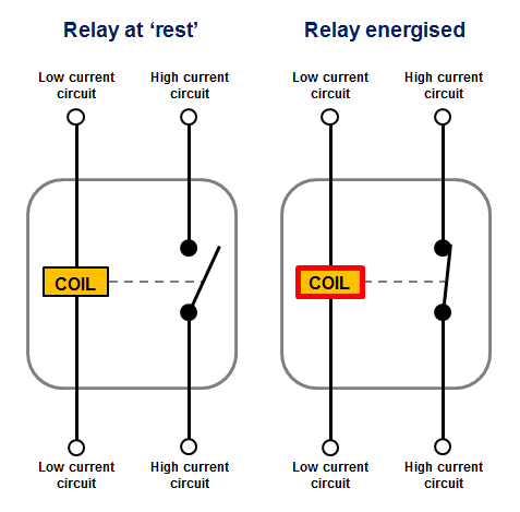
Before starting, a explanation as to headlight relay and parasitic drain. The electronics of the Polaris is designed for a keyed main power relay, the Versys has no such thing, the regulator has full battery voltage to it
all the time . Since the design of the Polaris depends on correct polarity as to
+ - and the control of the output uses the same
+, there is a conflict, as the Versys headlight uses one of the 3 phase outputs to trigger the headlight relay.
You need to test the stator before starting, if you have shorted turns, adding a series regulator will free up power to hasten the failure of existing damaged windings, I don't want to hear someone say the Polaris caused damage , follow my post
Regulator/ Series / CompuFire / MK-1
I have come up with
4 options ( 2019 )to bypass this problem when installing either Polaris or CompuFire Series Regulators see post #3
Note October 2019 Option #1 is used mainly if you wish to leave the 3 phase stator plugs intact, you then need follow below, If you don't care about the 3 phase plugs, go to post 57 Option #4
Option #1 and #2 involve removing the gas tank #1 cut black pin #2 1.25" long and connect to gray 1/8 "striped insulation & soldering Pin#3 See Photo Verskpd#2 /
Screwdriver
Option #2 also involves using a diode, unless you are familiar with electronics , and don't want the headlight coming on until you are ready to ride, my recommendation is to steer clear of this option.
Option #3 involves buying a cheap 12 volt relay but the gas tank can be left in place.
I strongly recommend installing a voltage indicating device,heads up by signal dynamics or
neat little voltmeter as in my photo here
neat little volt meter, extremely accurate, day or night
Parts required & Tools
Triumph harness, T2500676 Triumph Link Lead, Regulator $9.08 - 2WheelPros
Using the Triumph Harness: Keep in mind, with the harness you have a additional 5 connections, you will need to cut the connectors off the end that would go to the stator, and butt splice or solder these 5 connections.The two insulated 10 gauge but splice crimps and three 14 gauge insulated butt splice crimps, are required when using this harness ( if you wish to solder that would eliminate the crimps). Several people have stated they found it easier to use the Triumph harness. I now
recommend going this route, many don't know how to crimp and the Polaris is a bit of a oversize spade.
(
I no longer recommend this)----if you plan on going with the OEM wiring and no after market harness; you need two insulated 10 gauge female spade stakon crimps and three 14 gauge female spade insulated crimps, ( 2 insulated 10 gauge butt splices , 3 insulated 14 gauge butt splices or solder in place of the crimps ) some silicone, 3 feet of 16 or 18 gauge wire, also 16 inches of #10 stranded insulated, plastic sandwich bag if you are
not using the Triumph harness.Using 1/4 inch female spade stakons direct to the Polaris, expect to need to open the very start of the spade connector, as the Polaris male spade connectors are oversize in thickness, using electrical grease sparingly is also a good idea in either case of install.
I used a wrap of electrical tape around each spade connector, this allowed me to pump in silicone into the cavity , I reverse the tape after the first wrap, sticky side out, using half laps refereed to as reverse taping and the purpose of the sandwich bag.
Before you start, remove the positive battery terminal , instead of the main fuse.
Wiring of Polaris colour code, looking at inside male spade terminals, grey socket on left, black output socket on right. Left grey socket is 3 phase input in any order, that is the 3 black wires . Black output socket is left terminal Positive output, OEM Kawasaki Positive wire is white with a blue tracer. Black output socket right terminal is negative output, Kawi colour is black with a yellow tracer.
This is a 07 using the older non Triumph harness method
Again this is the old method, I released some slack in the harness close to the throttle cable, gains about 8 inches of extra wire length. If you had a Triumph harness , butt splices or solder would be in place of the female spade crimps.
Also note the brown wire is taped to protect it, as it is no longer reguired unless you wanted to use it to power led lights from a key switch.
Have a close look at the white/ blue, you will see the black electrical tape on the yellow insulated sleeve, I did one full wrap over the female spade part ,this was done because fully insulated stakons wouldn't fit inside this socket and was done to prevent silicone from entering this area, anyone that has used silicone knows how hard it is to remove once cured
this is the DIY before the Triumph harness was discovered. Notice the brown wire remaining in the harness, this was a keyed control on these early versions, needs to be isolated / taped.
The following photo was before triumph and back or reverse taping, this allows easy removal later, a sandwich bag was used and all the connectors were pushed through a small hole in the bottom, silicone was pumped into the socket and a small amount into the bag, which was taped in place onto the regulator, then the silicone was formed, last reverse tape this later a matter of scoring the tape, once the silicone cures the tape is redundant.
FYI if you make a mistake on the output wires, that is put positive where negative should be **good news, you get nothing outputted , also if you connect all 3 phase, start the bike and don't have both positive and negative connected and also to a battery with a minimum 8 volts, again you will get no output.
This is for option 2, view of my 2015, however all years are similar, note the red clip holding the fuel line in place, I describe this in detail in my valve shim thread. No room in this post as I have a limited # of characters .
So much discussion in previous posts about the diode, if you are not planning on using a diode, see wiring diagram Page 16-80 of the service manual ( 2015).
You need to cut the black wire pin#2 of the center headlight relay, like in my following post. Without a diode there is a 70% chance of the headlight coming on before you hit the brake, remember the headlight relay latches into the on position and will only turn off by hitting the start button or turning the key off, just a FYI. I like to bring the battery up to full charge while warming the bike up and also the load on the motor is reduced, there is a downfall to this circuit, on 2 occasions I have started the bike and was in gear, never touched the brake for 3 KM, and had no headlight, but I have Denali lights on all the time.
View of the relay box 2015 Versys Photos
Top of 2015 showing the fuel tank rubber mounts, tank slides back to remove, also shown is the connector going to the front brake
Front brake connector , note purple wire I added for my headlight relay trigger cct. also note the blue with red tracer is the brake signal and a small piece of insulation was removed and I soldered the purple wire to it
Verspkd #1
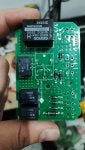
So the relay box end , center connector is the headlight relay, below is the connector with pin #2 black wire about to be cut and my purple trigger wire waiting to be soldered
Verspkd #2 Note the Black pin #2 and gray pin#3 with the screwdriver between
here is the purple soldered to the old 3 phase output #1phase wire, pin #2 black, which has been taped the same as the brown wire, no longer needed, but still powered
If you look real close you will see the black wire taped with yellow tape, I use yellow as it is a standard for external live parts and gets your attention
Joint is taped
A trick to taping in confined spaces using a tool such as this bent screwdriver